You will find the latest news and developments on the fabrication and construction of the Dynamic Earth Hydraulic Air Compressor Project on this page. Why not bookmark and come back often?
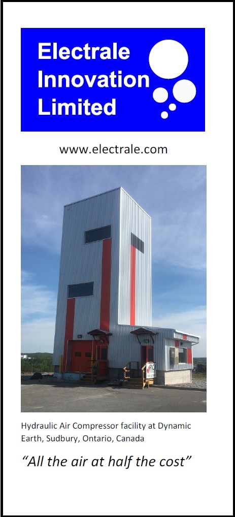
Considering a new mine compressor installation? Download our leaflet.
If you would like us to complete a preliminary technical assessment and appraisal for your site, email Dean Millar directly to set up a call to discuss at: dmillar@electrale.com
September 20th, 2019. We are very grateful to the Centre for Excellence in Mining Innovation for the opportunity to contribute to their Future of Deep Mining Conference, in downtown Toronto. Met up with some old friends, like Charles Haythornewaite of Chrysalix Venture Capital, who over was over from London, Steve Hardcastle of BBE, Sujeet Sengupta (Coleman Mine), and Negar Saeidi (Mine Ventilation) both of Vale, Canada, and Shannon Katary of Maestro Digital Mine. I also met some new friends like the dynamic Ritika Sinha, the wonderfully titled “Chief of Everything Officer” at ikonnect. This is Dean presenting on work enabled by BC Hydro’s PowerSmart Alliance for New Gold on an End-User Assessment of a HAC for New Afton Mine.

Photo credit: S.Espley
September 16th, 2019. Demetra Envangelou has come up with a new perspective for the HAC Demonstrator. She has devised another great selfie opportunity at at Dynamic Earth! Detmetra has just started a new adventure on the undergraduate program at Laurentian University’s McEwen School of Architecture. A student group from the same program designed the exterior of the facility 3 years ago. I am so pleased it caught her eye! I might just use this shot in my talk on Friday.

September 12th, 2018. International Mine Ventilation Congress in Xi’an, China. On behalf of Laurentian University, Dean Millar will be making a special presentation called: “Performance map of the hydraulic air compressor installed at Dynamic Earth, Sudbury.” If you are attending the congress, or are in the area, the talk is on in Congress Room 1 in the session between 15:30 and 17:15. If you can’t make it, then a copy of the slide deck is available here or by clicking on the slide below.

May 2nd, 2018. By means of the performance testing of the Dynamic Earth HAC over the past year, our understanding of the process has improved hugely, and designs for mine-scale HACs are at the forefront of our minds. Click on the picture below to link through to the YouTube video. The video shows a 0.5 m high transparent HAC in operation. We call this one the “PortaHAC” or the “MicroHAC”. The model simulates a HAC installation occupying a single raise in a mine, with circulating pumps at the top. Note that in this guise, we have dispensed with a forebay tank, and the air water mixing head is in-line. This simplifies design without compromising performance while reducing cost. The air water separator chamber is fully immersed in the riser (the “mine raise”) and is open-bottomed, and yes, I did fill the MicroHAC up with the drinking water from the bottles visible on the right which went straight to recycling.

March 21st, 2018. “What’s the craic at the HAC?” Over the past 8 months we have learnt a huge amount about: 2 phase flow, isothermal gas compression, bubble detrainment and re-entrainment, what happens when we try out different air-water mixing heads and what happens when we put salt in the circulating water of a HAC.

Come and chat with the ‘HAC Pack’ during our open house event at the HAC Demonstrator at Dynamic Earth to find out about the latest news and results. 5pm to 8pm. Part of Laurentian University’s research week.
December 4th, 2017. Want to drive the HAC Demonstrator? All you need to know is contained in the HAC Operator’s Manual which Steve (RHS) has just finished compiling. All that we have learned to date has been centralized into one, fat, indexed, binder. As the current HAC pilot, Justin (LHS) has distilled his experiences into the document.
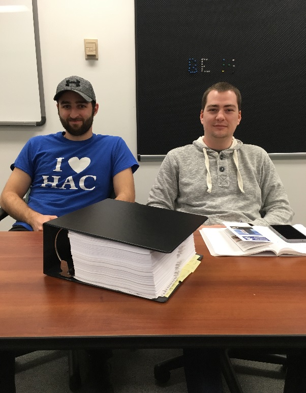
Looks like a cure for insomnia to me! It is much more fun to drive the HAC rather than read about it. If you would like to visit, contact: dmillar@electrale.com
November 27-28th , 2017. Valeria, Caterina and Dean attended the Energy & Mines World Congress in Toronto. At the Congress, we launched our new HAC brochure. If you were there, perhaps you got a copy with the spelling mistake on the front page! Download a copy of the brochure without spelling mistakes here.
 If you are downloading and want to print it out, it’s best on a duplexing printer. Via Acrobat, select “flip on short edge”.
September 27th, 2017. Gosh! We have been busy since the opening back in June. Today, at CEMI‘s Annual General Meeting, we will share with the audience assembled at Dynamic Earth, some of the things we have found out about the HAC over the summer. A copy of the slide deck (with a few extra slides not presented at the talk) is available right here: DLM CEMI AGM Presentation V3. Videos used in the presentation are available on the HAC Discovery Channel page.
June 21st, 2017. At 4.00pm today, we had the opening ceremony for the HAC Demonstrator at Dynamic Earth. We are hugely grateful to all who joined us for the ceremony, tours of the facility and the BBQ networking opportunity. Thank you.

L-R: Dominic Giroux (President, Laurentian University), Mayor Brian Bigger (City of Greater Sudbury), Julie Moskalyk (Science Director, Science North), Bora Ugurgel (Ultra Deep Mine Network, hosted at CEMI), Honorable Glenn Thibeault (MPP for Sudbury and Ontario Energy Minister), Declan Doyle (Independent Electricity System Operator), Guy Labine (CEO, Science North), Dean Millar (MIRARCO, Laurentian University and Electrale Innovation Ltd)
‘Twas a wonderful event, especially because the weather behaved itself, the HAC produced loads of compressed air throughout the day, and the BBQ food was very tasty. The biggest thanks go to Shannon Katary who masterminded the whole day. The event created quite a bit of media coverage. Hit the links below to find out what people are saying about the project.
Northern Life (Sudbury.com) article

We are also grateful to those who helped us create this Hydraulic Air Compressor and who wanted to be there for the opening, but for whatever reason could not attend. A copy of the slides used in the “What the heck is the HAC?” presentation is available here: 2017 06 21 HAC Demonstrator Opening presentation
June 18th, 2017. MIRARCO ‘Combat’ programmers Steve Young and Justin Sivret concentrating on their respective codes in the control room, while the control room gets fitted out around them. Steve is coding a procedure we are calling ‘closing the loop’, where his model of the downcomer two-phase flow hydrodynamics coupled to solubility / psychrometry physics is being extended to be able to be applied to the whole HAC circuit. Justin is working on the Human Machine Interface (HMI) for the HAC control system, responding to requests for increased visual feedback, new real time charts of HAC state variables and testing of control procedures. Both are using MATLAB. Eventually it is our intent to run the simulator and the HMI side-by-side in real time, so that convergence between the two represents our improved understanding of the processes.
Later in the day, we are confident enough to subject the system to some operational trials. The shot below shows the water entering the header/forebay tank from the two delivery pumps during a procedure Justin wrote that aims to test the blow-off safety valve. The water looks pretty mucky.


June 17th, 2017. Morning shift was at the site from about 9.00am and cleared out the control room for its fit out. Afternoon shift showed up at 2.30am and started sealing the floor, painting the walls and erecting control room benches. Later in the evening we paused to watch the superb multi-media experience that is the Big Nickel Show with other visitors to the Dynamic Earth site. Then we welcomed some visitors to the facility: Peter Pakalnis and Victor Pakalnis. Peter was visiting his Dad over the weekend for Father’s Day and had come to Dynamic Earth equipped with a drone. We asked him to take some footage of the HAC from the air, and the video above is the result. Sincere thanks Peter – this is an absolutely amazing video.
June 16th 2017. Fire inspector Doug and Chief Building Inspector Tony took a look around the facility this afternoon. Occupancy certificate granted!! We are good to go.
June 7th, 2017. It has been a very busy time, getting the facility complete and the system ready to run. The latest exterior shot is below, and this is shows the final exterior look of the facility. Smashing!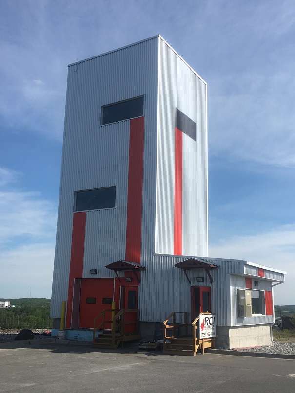
From the outside, all looks pretty quiet, but inside we are busy undertaking preparation and some commissioning tasks. We are able to do some advance work when the Contractor is not working on the site. The system is not started yet because there are still instruments to install, and even some of the smaller diameter pipework to fit. But we are getting there. We are learning about the process of finishing the build phase of a development having been preoccupied with fire safety inspections, Electrical Safety Authority inspections, commitment certificates, site safety inspections, the list goes on. The main thing we are aiming for is the occupancy certificate, and we are hoping this will be received next week after more a few more look-arounds and inspections.
June 5th, 2017. The official opening date and time has been set: June 21st, 2017, 4pm. For anyone viewing this page, this will be of interest, and so let me extend an invitation: you would be most welcome to join us to celebrate the opening of the facility and the start of test runs. Just let Kelsey Bastien, of MIRARCO, know that you would like to come: kbastien@mirarco.org.

We are all deeply indebted to Shannon Katary, Director of Marketing & Communications at the Centre of Excellence for Mining Innovation (CEMI) and the Ultra Deep Mine Network (UDMN), and also all-round event mastermind, for directing and coordinating the event. When Shannon is in charge, we all know its going to be a great event!
May 26th, 2017. If there is a ‘secret hot sauce’ that makes the HAC tick, this is it – the air-water mixing head. This shot shows the designer: Alex Hutchison and the fabricators: Robbie Duncan and Andre Roberge photographed with the Taylor Head in-situ in the header / forebay tank at the top of the Dynamic Earth HAC.

Alex’ design was inspired by his Voyage to the Centre of the HAC at the Peterborough Lift Lock HAC, where he saw the original air water-mixer head, designed by Charles Taylor. This one has the same key dimensions, but was fabricated with modern materials and methods in the Cambrian College workshops where Andre and Robbie are both Faculty members. I understand that they had quite a bit of help from the Cambrian College students under their direction too.
May 19th, 2017. Friday evening, 5:42 PM, collar elevation, Dynamic Earth HAC. I think I look happy, but I am not sure. I recall having butterflies: the big pipes are in, but there’s still a fair way to go, and the HAC Pack has a weekend’s worth of work ahead. In the week that has just passed by, Talevi Welding and Mechanical have been working marvels. Colin, Colin and Larry have fearlessly been fitting as much pipe as we can provide them with. The pipework has all been fabricated by Fuller Industrial.

Braden and Jeff of Fuller are at the base of the pipe-work pipe-line. For the 4″ pipe delivering compressed air, once the pipe has been fabricated including rubber lining, then it needs to be inspected and approved by the Technical Standards and Safety Authority (TSSA). After that, it can be delivered to the site so that Colin, Colin and Larry can lift and swing the section into position, and fit the pipe using state-of-the-art couplings supplied by Victaulic Canada, one of our core sponsors. The large sectioned pipe uses special Advanced Groove System (AGS) couplings.
All the pipe touching water needs either to be made of stainless steel, or carbon steel that is rubber lined. This is not because we expect the water to be particularly aggressive as a working fluid when the HAC is in operation. Rather, it is because we will be dissolving some co-solutes in the circulating water to inhibit the dissolution of the compressed gas. This is part of the Demonstrator’s technical brief. As part of the program we will demonstrate how the addition of a co-solute improves the compressed air yield of this modern HAC system in comparison to its 100 year old counterparts. As a precaution, all the pipework has been designed with corrosion protection in mind – and this is where the rubber lining comes in.
In the background on the left, you can see that the twin variable frequency drive (VFD) units have been installed. These were supplied by Rob Vaillancourt of Sling Choker Ltd. These are powered by 600VAC power and are ‘smart’ in the sense that their performance has been tuned to the pumps we have selected. Electrical installation work has started on site.
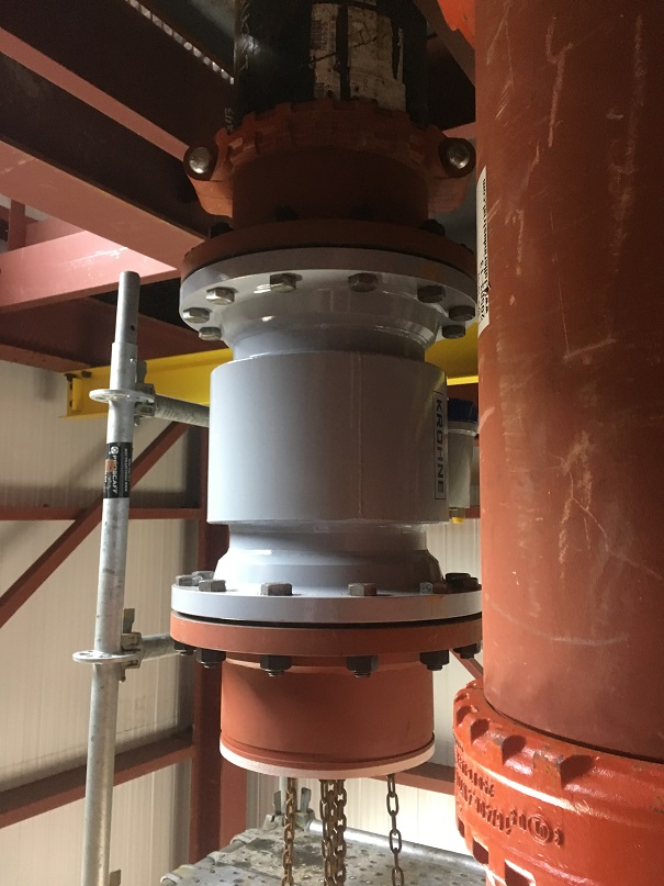
5th May 2017. It may just look like a section of grey pipe, but actually this shot shows one of two 12″ diameter Krohne Optiflux magnetic flow meters. One of these is installed in the pipe on the delivery side of each of the two pumps. These are the biggest flow meters I’ve ever seen! They are around 100kg each, so their installation has to be undertaken by professionals. In this case it was Talevi Welding and Mechanical. These are very accurate too: +/-0.15%. Of all the variables we will be be measuring around the system, the water mass flow rate is probably the most important.
April 26th, 2017. The final look of the building containing the HAC starts to materialize. I hope I don’t have to explain! But I will anyway – because I have been asked frequently in the last couple of weeks.

The orange paneling on grey paneling was devised as a pictogram on the exterior of the building of what is contained within. Student Architects from Laurentian University’s McEwen School of Architecture, overseen by their Visiting Prof. Roch Belair, designed the exterior look of the HAC Demonstrator at Dynamic Earth. Although it is not quite completed yet, I think is it fabulous, and a model of scientific communication through physical form – all done on a close to nil budget.
20th April 2017. We are becoming regulars at Castle Plumbing and Heating, behind the westbound Tim Horton’s on Lorne Street. We go there frequently because we can describe what we want to them – in rather vague, ‘unplumbing’, terms. Then they dissappear into the back, and bring forth items that were exactly what we wanted, or a close match. Valeria and I are recognised as we enter, and are regarded with welcome caution by the team there. What was is not spoken is: “Uh-oh! What do those guys want from us again!”
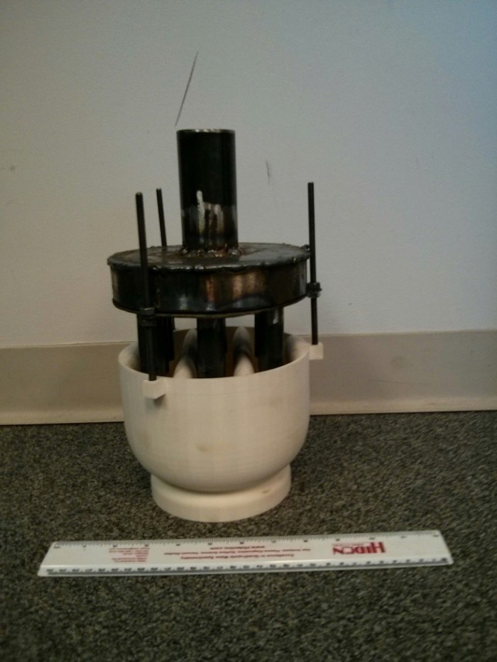
Today’s sojourn to Castle was, again, fruitful as it produced exactly what we needed to form the needle valve housing for the gas-liquid sampling separator that we have made, and which is shown below. This is an absolutely crucial item of equipment for us, and with the needle valve installed, the whole sampling system worked like a dream.
Sampling probes can be inserted into the downcomer pipe through a gate valve. The probe has been designed to ‘suck in’ as much gas phase fluid (the bubbles) as possible, with a minimum amount of liquid phase fluid (the water). The mixture passes through a annular duct in the probe and out a side tapping to a tube that passes to roughly the centre of the separator. This is the transparent cylinder on the left of the photograph. The liquid spins and falls downward (it is a gravity separator) into a sump from which the liquid is drawn to a pump (the pump we use is normally used to cool CPUs on high end PCs). The liquid is then pushed into a coaxial pipe in the sampling probe that reinjects the fluid into the bulk downcomer flow. The principal benefit? No mess.
At the separator, the gas phase rises and passes-by the needle valve to a duct that leads to the mass spectrometer where the gas is chemically analysed. If too much water enters the separator, the water level rises, lifts the float which closes the needle valve. If the water level in the vessel gets to low, a capacitive water level sensor sends a signal to an Arduino ‘brain’, which turns the pump off, while the gas in the vessel flows out to the mass spec.
We chose an Arduino because we were able to program PID control of the pump with it, and for another 15 bucks were able to add a WiFi board to it, so it can inform us of the status of the gas sampling unit from the control room. Credits: Valeria Pavese, Tom Clifford and Peter Moutsatsos.

25th April, 2017. The team in the Cambrian College workshops have worked their magic for us. Alex’s design for the air-water mixing head has been fabricated and was delivered to us today – and an absolutely smashing job they have done with it too! It is shown here with lower part on the LHS pallet and the upper part on the RHS pallet. When in service the upper part is held above the lower by the vertical three mounting/spacer bolts which can be seen ‘sticking up’ from the LHS item. A thoughtful addition to our design by the Cambrian team was a temporary cylindrical plate to protect the hundreds of air induction pipes on the underside of the upper part – while it is in transportation. Unfortunately you can’t see these in this shot, but see below to understand what is inside the fat cylinder.

18th April, 2017. There is a great deal of work going on inside the building now. This shot is taken on top of the tailrace tank on the pump deck, looking down towards the vertical ladderway. The motor to one of the two pumps can be seen just to the right of the ladderway, partially obscured by the vertical downcomer pipe – which has now been connected to the forebay tank above.

April 6th, 2017. This video starts slow, but is worth watching right the way through to the end. The video is not about the Dynamic Earth HAC, but is about Ragged Chutes, and is so good, it has made it to the ‘latest news’ page that most people see first on this site. William Sutton has made a gift to the world in publishing this video. Simply inspirational.
March 30th, 2017. Flynn Group of Companies are supplying and fitting the architectural cladding of the building. The photo below shows the inner liner being affixed, not the final finish of the building exterior – so no hint on the colours yet! The insulation layer and the outer, weather resistant, layer of the building envelope will be applied over the liner in the next couple of weeks. The building as a whole is starting to take shape.
With some of the cladding in place, we can present the first shot taken from the inside of the building looking out (below).

The top half of the riser pipe, to a short spool piece, can be seen on the left hand side. We have deliberately retained short sections of pipe such as this in order that they can be swapped out for advanced sensors to monitor the process – in the coming years. What I have in mind for this section specifically is a tomographic based two phase flow sensor that will map bubble trajectories in real time. We also want to see if it will be possible to monitor gas bubbles forming as they come out of solution when the flow depressurizes on its way back to the tail race tank.
March 27th, 2017. Had a communication from one of our initial HAC buddies today: Dan Larocque who I met at the Bunker Museum in Cobalt a few years ago. Dan is a curator at the museum and was in touch to send through some fantastic aerial photographs of Ragged Chutes. Dan has said it’s OK to share the photos on this site, so here you go!
Dan has also produced a “must see” video: 5 star review from the HAC Pack.
Fantastic! Thank you so much Dan.
First, an oblique shot showing the compressed air pressure regulation station. Compressed air, from the capturing plenum ~85 metres below the depth of the Montreal River at this point, passes up the air delivery pipe (mounted within the riser shaft) and runs up the cliff to the station. From here, the air passed to a compressed air main, around 14 km to heart of the Silver mining town of Cobalt.

Secondly, a vertical overhead shot of the forebay tank containing the twin air water mixing heads (that fit into the twin downcomer shafts). The ‘shed’ spanning the top side of the fore bay contains gate valves that could isolate the river inflow from the system for maintenance.

Thirdly, an aerial oblique that peeks into the forebay tank, where one of the two air water mixing heads is clearly visible. The photograph looks surreal that the forebay area is full of snow; this would not have been the case during winter in operation. The beams one can see spanning the forebay acted as supports for the pneumatic rams that lifted and lowered the air water mixing heads, according to the level of the river over the seasons.

March 22nd, 2017. Pretty much all the steel is up. The header/forebay and tailrace tanks are now in position and the centrifugal pumps have been lifted onto the tailrace deck ready for fitting. 2 tonne (yellow) lifting beams have been fitted. Site foreman, Dan is currently waiting on additional pieces to be erected around the frame, right at the top of the building and these will help to support the roof. The crew from Talevi have been busy with pipe alignment and fitting in the shaft in the past week or so.
There is some discomfort about the open hole on each deck that forms the lifting well, despite the fact that all personnel would be behind railings. So grating panels are being designed to close these holes for routine operations. Safety first!
Dean is shown in the shot below, looking at some information boards prepared by Julie Moskalyk and Jennifer Beaudry of Dynamic Earth. These were drafted to brief visitors to Dynamic Earth during March Break week.

March 22, 2017. Visit to the Cambrian College mechanical and metalwork workshops to assess progress on the fabrication of the Taylor Head for the Dynamic Earth HAC. This is another example of how Laurentian/MIRARCO and Cambrian are working together.
This particular shot is called: “Made in Italy”. This, of course, refers to the lathe Valeria is pointing to, rather than Valeria herself! Andre Roberge, Robbie Duncan, Mike Commito and Emile Malvasso of Cambrian were our hosts for the visit. Robbie said that this was the best lathe (of many lathes) in the shop, which brought a smile to Piemontese Valeria’s face. Machines were not operating while we were visiting. Safety first!

170 of these pipes are going to be screwed into an air manifold base plate to form the secondary inlet for the air-water mixing ejector. Don’t bother counting them! There are a few more resting on the trolley behind the bin – out of the field of view.
This computer controlled milling machine is going to drill and tap the holes in the base plate. Although it is computer controlled, it’s actually going to be a tricky process because the base plate is just a little broader than can be accommodated by the machine for drilling all the holes in one sweep. The plate will need to be reset and re-aligned twice to drill them all.

The shot below shows the convergent duct below the hydrofoil blading that will span the water inlet. The hydrofoils are mounted close enough together than they form convergent-divergent nozzle passageways. When the water passes through, the Bernoulli effect will create a low pressure zone at the throats of the nozzles. This will draw in the air from the air pipes suspended just above the hydrofoil blade array.

Below there’s a shot of one of the blades that will span the converging section above. Andre has devised a way to bend the blade form with a press. Looking good!
March 8th, 2017. VIPs attend for a tour of the BabyHAC lab as part of celebrations of an announcement of research collaborations between Laurentian University and Cambrian College. The best part of the day was Alex’ interview on CTV aired later that evening. He didn’t take his ear muffs off for that either! Watch the video here.

March 7th, 2017. The Reasbeck Construction Inc. team were very busy today making the HAC Demonstrator at Dynamic Earth start to look like a proper building.


February 27th, 2017. An absolutely beautiful winter day at Dynamic Earth for the team from Reasbeck Construction Inc to execute the precision lift required to fit the underground modules onto the collar steel. The picture above shows the modules, prefitted with the large diameter pipework, held aloft by a 80 tonne capacity crane. The smaller, 50 tonne, crane was required to lift the tail of the assembly off the ground, while the larger unit brought the assembly to the vertical – or near vertical.

The module assembly had to fit into the rectangular aperture formed by the collar level steel beams (photo above). According to our designs, there were 80 mm clearance between the expanded metal mesh and the aperture – plenty enough for the modules to pass down to the shaft!

80% down: the last module passing into the shaft. The photo below shows that after the modules cleared the collar, they still had to fit snugly within the meshing around the shaft collar that had been installed few weeks ago.

As the modules were not quite hanging vertically from the crane, they did meet an obstruction towards the end of the lift, and this required some maneuvering, manual manipulation and adjustment to get around it, but by the end of the day, the complete assembly was in position and was being bolted to the collar steel (below)

It’s down! And it fits! The Reasbeck Construction Inc team landing the Dynamic Earth underground modules on the collar steel. Great job guys!

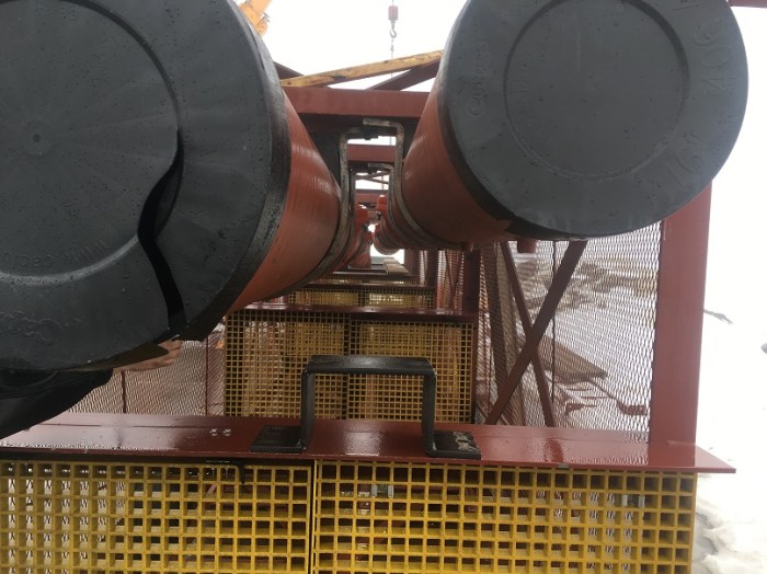
February 23rd, 2017. Busy weeks, sometimes frustrating weeks, but we are making progress! Earlier on this week, the fantastic Victaulic Canada delivered the pipe couplings. The 24 inch couplings (0.61 m, for those more comfortable in metric – like me) are monster-sized. The Victaulic grooved couplings provide just the right amount of accommodation for thermal expansion of the system in service. If we have got our sums right, this Hydraulic Air Compressor will have greater compressed air yield if we run it hot (actually, we’ll limit it to around 60 degrees C) – because less of the compressed gas will dissolve in the water. Led by the indefatigable Justin and the indomitable Larry both of Talevi Welding (taleviwelding.com), precision fitting of the pipes to the underground modules got underway immediately – ready for a big lift underground on Monday. The photo above was taken yesterday, and shows the 16″ to 24″ diffuser (divergent) section being mounted. This part will fit to the downcomer nozzle into the air-water separator. Its function is to start to slow the gas-water mixture down, so that bubble buoyancy forces dominate over drag, and the bubbles lift out of the water to form a plenum above the swirling water in the plenum.
The shot below shows the view from the other (top) end. Each pipe section has several theadolet nipples into which we will insert gas/water sampling probes, ultra-sensitive differential temperature sensors and pressure transducers. These can be seen on the 16″ pipe on the right hand side.
The air-water separator had to be pressure tested. The nozzles (the pipe entries and exits) were capped off, the separator was filled with water (just under 10 tonnes) and the water in the vessel was pressurized. No leaks! All OK!
This is the amazing team of welders from Hanking Mechanical (www.hanking.ca) who stitched the air-water separator back together, in-situ! The fit of the vessel at the shaft bottom was so snug that it was not possible to get access all the way around to make the welds. As a result, the accessible welds were done, the vessel was lifted a few inches with a crane and rotated 180 degrees, and then set down again. Then the remaining welds could be done. The biggest challenge was keeping the welding areas dry, in the face of the groundwater water entering the shaft at the collar level. Tarps kept the water off, and propane heaters kept the metal warm while the welds were completed. This shot was taken on Friday 10th, after the welding was complete and the team were heading out for some refreshments. Great job team!

February 9th, 2017: More cheers break out. Justin sends through a video of his first App Designer HMI screen for the pump power metering. All key components of the SCADA system proven to work with one another. Click on the image to see the first signs of life of the HAC at Dynamic Earth. Go Justin! Go!

February 7th, 2017: Valeria, Steve, Justin (who has been ‘borrowed’ to help out for a few weeks) and Caterina hard at work at the Cambrian College lab in the Glencore Innovation Centre. Valeria is live testing gas sampling / gas separation systems on the Baby HAC. Occasionally she gets a little damp! Caterina is running calibration protocols on the mass spectrometer that will analyse the gas, and is preparing a big report that will summarize and review the performance we can expect of the mass spectrometer gas analyzer. Steve has handled the specialist instrumentation procurement process, and will be bringing the new instruments into operational condition as they arrive. The latest arrival is contained in the aluminum ‘suitcase’ on the table to the right in the photograph. It is a mechanized control valve that will regulate the amount of compressed air delivered by the system at Dynamic Earth, so that the level of the water in the separator remains relatively steady. In the lab, the unit is wired into the panel, so that instrumentation, signal, and actuation channels can be all be checked. In the past weeks, Steve has also designed a stilling well to accommodate a guided wave radar water level sensor, which will tell the system how much water is contained within the separator. 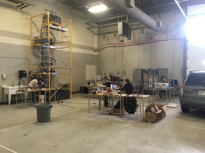
After Tom passed his Comprehensive PhD exam he was straight back into the lab to bring our TopServer OPC system up and to verify the data acquisition system. Software Toolbox’ TopServer makes it straightforward for the computers to ‘talk to’ the instruments and actuators through the hardware ‘spaghetti’. We are going to be using MATLAB to coordinate sensing and control via its OPC toolbox, and its AppDesigner Human-Machine Interface (HMI) authoring tool. There were cheers all around, and a significant milestone achieved, when we witnessed the OPC tags populating our data structures in MATLAB. We needed some additional expert help from IT ‘Guru’ Mike to sort out what we thought were DCOM issues that were preventing network communication with the mass spectrometer. But Mike got it licked: it turned out there were some LabView ghosts lurking within some of the mass spectrometer software that needed special coaxing; the notorious DCOM wasn’t actually the issue. Justin, supported remotely by Tom and Andy, is now leading the charge on creating the HMI screens, and coding the Dynamic Earth HAC ‘brain’: the PID logic between separator level sensor and air delivery control valve.
February 5th, 2017. It has been a challenging and exciting week that culminated in the air-water separator unit being fitted into position at shaft bottom of the Big Nickel former elevator shaft. In order to fit, the air-water separator had to be cut into 3 parts: the base, and two half shells. In this photograph, the base has been precisely positioned into the arresting pit for the former elevator, and the first of the half shells has been precisely fitted onto the base, using an orienting ‘key’. The orienting key for the second shell is a small vertical pin, visible on the lower right hand side of the photograph


Some difficulties were encountered with the ground conditions at the site which meant that there had to be a rapid redesign of the facility foundation (thanks to Black Rock Engineering and Makami Engineering, the Project Engineers for this). However, we have been lucky. The warm weather in January has permitted a degree of catch up. Concrete was poured for the footings, foundation walls of the main structure and the adjacent control room on Friday 23rd January, 2017. Instead of being -15 degrees as would normally be expected for the time of year, the temperature was zero! RCI commented that it was like they were building in November. Just as well – this part of the HAC project started a bit late!

Before: the foundation concrete pour.

After: Reasbeck Construction Inc. have done a fantastic job in accelerating construction, even in the depths of winter. This is our favorite shot so far, with the Big Nickel in the background.
All the scientific instrumentation for DE HAC needs to be integrated for the measurement and verification work that takes place shortly after the construction phase, and for the scientific investigations. The shot below shows Robin and Stephane of Ionic Engineering, also of Lively, Sudbury, who have produced some absolutely beautifully laid out control panels for the facility. The panels have now been transported to HAC Lab at Cambrian College, where the data acquisition and control instrumentation for the machine will be set up for service.

Completion of the control panel for the Dynamic Earth HAC at Ionic Engineering
As well as simply proving that compressed air can be produced far more efficiently with a HAC than modern mechanical compressors, as a springboard to large scale commercialization, the Dynamic Earth HAC is being equipped for some ongoing advanced engineering science. For this, we need access to the full height of the downcomer pipe of the system, in order to insert our probes, samplers and other instrumentation. For this reason, the HAC we are creating at Dynamic Earth has full ladder and platform access, which will not present on our commercial models. The sub-surface structural components are being fabricated in modules, an example of which is shown in the photograph below. These modules will be bolted together before being lowered into the depths of the shaft.

One of the sub-surface structural ‘modules’ that will support the downcomer, riser, blow-off, and compressed air delivery pipes as well as instrumentation platforms. The expanded metal on the outside of the module will protect the engineers and scientists working inside from the risk of spalling rock from the shaft in which the module will be installed. This one is shown being prepped for painting in the paint shop of Nickel City Steel who are the steel fabricators.
The picture below shows the separator for the Dynamic Earth HAC. It is a 3m high, 2.5 m diameter stainless steel, custom air water separation vessel designed by Alex Hutchison, fabricated by Specialty Alloys and Stainless, Lively. This vessel having been fully assembled in the shop, then needs to be cut in half in order to pass down the shaft to the Big Nickel Mine at Science North’s Dynamic Earth. Then the two halves will be welded back together before pressure testing and service. There are some sophisticated geometries, that required advanced computational fluid dynamics analyses, inside the vessel to help the compressed air and water separate.

The air-water separator for the Dynamic Earth HAC approaching completion of fabrication at the workshops of Specialty Alloys and Stainless Ltd, Lively, Sudbury. In real life, it is a lot bigger than it looks in the photograph.
7:30am on site in early November showing wonderful winter colours over Sudbury, Ontario. This was the first morning on site and Reasbeck Construction Inc., were starting to clear the site. Substantial completion of the build is expected in early May 2017 at which point ownership of the facility will pass from Electrale Innovation Ltd (who are the Project Owners) and Reasbeck Construction Inc. jointly to MIRARCO Mining Innovation and Laurentian University, the facility operators.

Reasbeck Construction Inc set up the site and start clearing the shaft area on the first day of construction
